Spindle, Control Panel, Bed, Tool Magazine, Axis, Chip Conveyor: Vital for precision, efficiency, automation.
Input Device
Input devices are vital components of CNC machine tools that allow operators to communicate instructions to the system. The typical input devices used together with CNC machines include a keyboard, a mouse, a pendant, a joystick, a touchscreen panel, and a remote control, among others. The functions of these input devices can be described as follows:
-
Keyboard as an input device: The keyboard is used to input numerical codes, commands, and parameters directly into the CNC. The convenient tactile feedback and the traditional arrangement known to the users facilitate efficient and accurate programming.
-
Mouse as an input device: A mouse is the most conventional device used to navigate CNC control software, select in the menu windows, and manipulate the graphic forms. The mouse facilitates the process of editing programs, forming tool paths, adjusting parameters, of CNC control.
-
Pendant as an input device: The pendant is a portable device with buttons, knobs in different directions, and a touchscreen; it is convenient to hold in one’s hand. Using the pendant, the operator can jog axes, start and stop operations, perform manual operations, and more.
-
Joystick as an input device: Originally, the CNC machine was equipped with a ubiquitous joystick to control them. The joystick is used to direct the machine movement in all the planes simultaneously.
-
Touchscreen panel as an input device: Nowadays, in addition to wires and joysticks on CNC, a touchscreen panel is used, the use of which is also as simple as the smartphone one. The operator can find any function, change the parameters, and press the button with a finger touch without using his/her thumbs.
-
Remote control as an input device: The remote as an input device helps to control CNC from a distance in huge spaces. For this purpose, the interfaces of remote controls are equipped with freely and ergonomically arranged wireless and intuitive buttons.
Machine Control Unit
MCU is the Machine Control Unit, which is the central part of CNC machine tools and drives different machine functions based on instructions. Here are the key components and their functions:
-
Processor: CPU or processor performs computation and interprets all the G-code instructions. It is possible to use general-purpose processors, such as Intel Core or AMD Ryzen series, to perform instructions quickly and in real time. Advanced features allow it to control CNC tools efficiently and accurately.
-
Storage: RAM and ROM modules for storing data of programs, machine settings, and system software. The capacity should be up to 4GB to 32GB to store multiple programs and enable smooth program execution.
-
PLC: It is the basic machine interface with other controllers, and its most critical functions are spindle speed, tool change, cooling, etc. It performs functions based on digital and analog inputs and outputs to enable precise timing of all functions. It utilizes feedback loops to detect errors and execute the correctaction.
-
Interface Ports: It is important to exchange data with other devices, input units, sensor units, and any other peripheral machine that is connected to the MCU.
-
Motion Control: It requires a system of stepper or servo motors, drives, encoders, and feedback loops to ensure precise control of every axis. More complex control systems should be used to control expansion, speed, and other factors. PID control is the most basic technology to ensure minimum acceleration, maximum speed, and position balance for different machining processes.
-
Operator Panel: Physical buttons, jog wheels, and projector screens can be used in the operational panel. The projected screen must be monitored for machine execution and parameters inserted by the operator. All of these features enable the operator to execute a smooth and efficient machining process. In a word, MCU is built on hardware and software, and their powerful architecture and application provide a reliable, robust, and highly dynamic and efficient control of CNC tools.
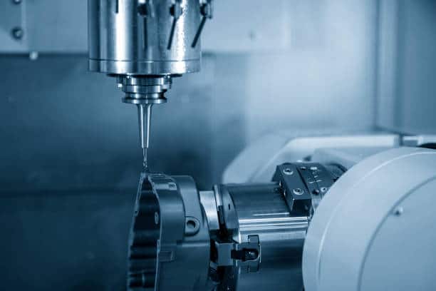
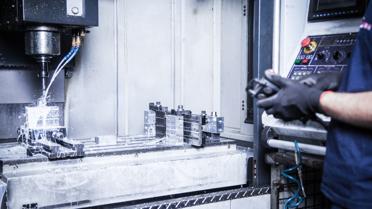
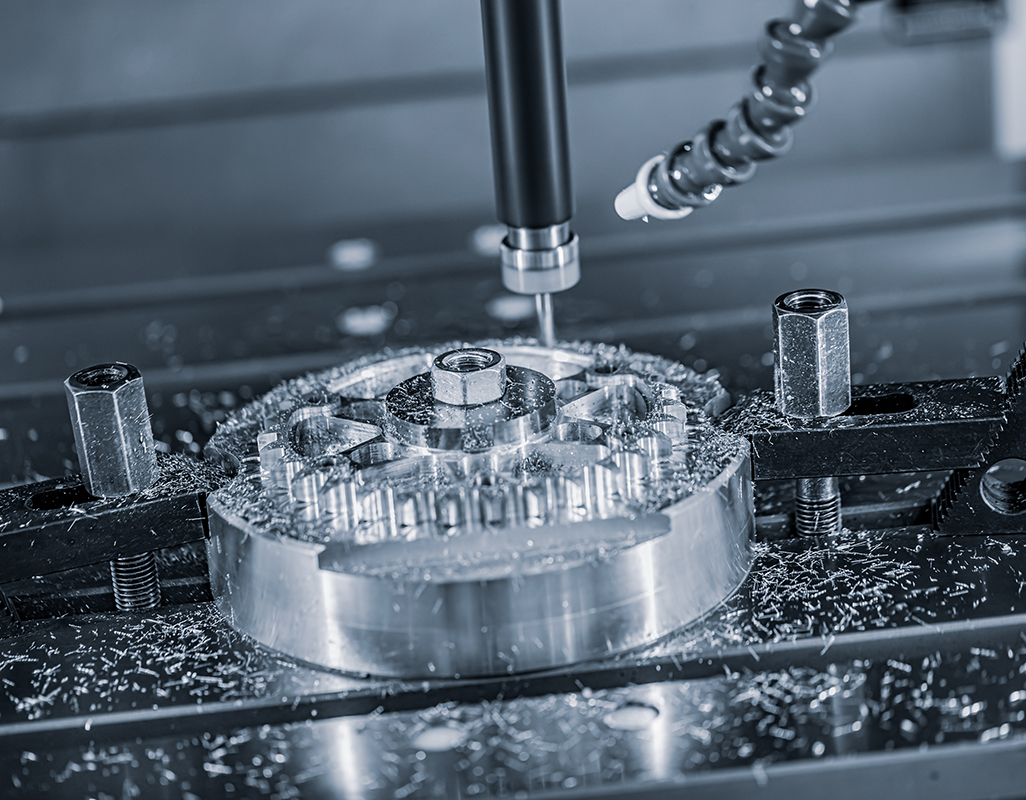
Machine Tool
Machine tools are fundamental to manufacturing, as they are specialized equipment designed to form, finish, cut, or shape metals, composites and many other types of materials. The main components of machine tools include the following:
-
Bed: this is the foundational base of a machine tool as it is used for mounting different machine tool components, such as the workpiece, spindle and cutting them. Beds are normally manufactured from either cast iron or steel to ensure stability and precision.
-
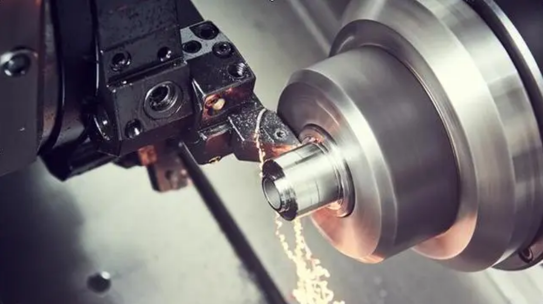
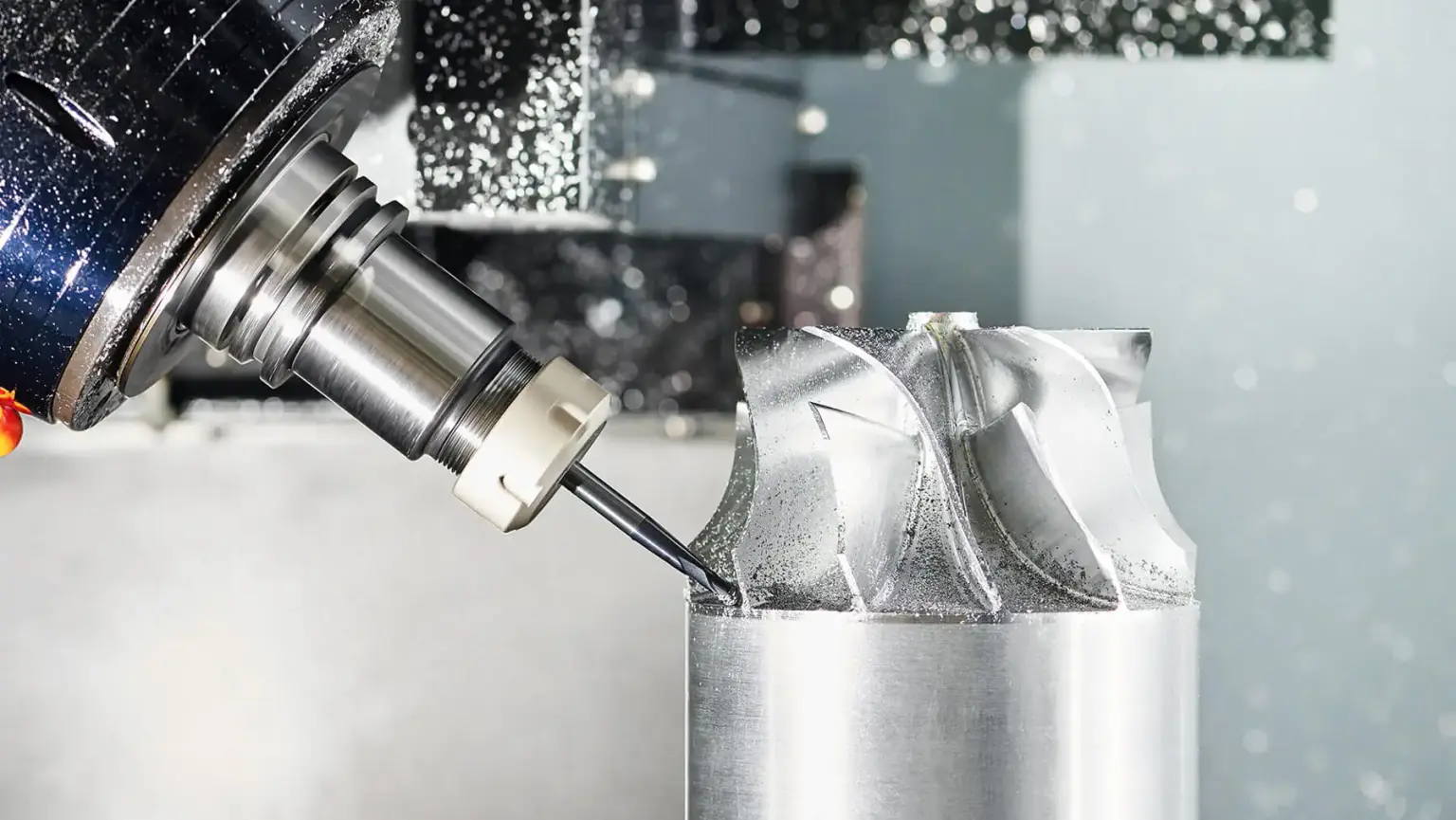
Spindle: this particular component is a shaft designed to rotate, holding and driving cutting equipment. A wide variety of the spindle’s turning speed is applied depending on its purpose – several hundreds of RPM for heavy cutting and tens of thousands RPM for high-speed milling.
-
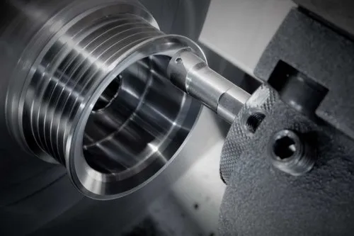
Tool holder: this element of a machine tool is designed to hold and grip cutting equipment and, at the same time, to ensure they rotate. The major different types of cutting hardware holders include chucks, end mill holders, and collets.
-
Cutting tool: another important part of a machine tool is cutting tool employed for removal or abrasion of material from a workpiece to form it into the correct final shape. The common types of cutting equipment is as follows: carbide insert, high-speed steel , and indexable face mill cutter.
-
Guide-ways: these provide linear motion for the spindle or other moving part of a machine tool and supports it. There are various kinds of sliding blocks available on the market, such as dovetail, box way and linear roller guides.
-
Control system: the machine tool operation is generally directed by this machine asset; it is responsible for coordinating spindle and feed rate, as well as the movement of the cutting tool. Present-day machine tools are driven by CNC.
Drive System
A drive system is one of the most critical components of machinery as it converts electrical, hydraulic, or mechanical energy into motion. Some of the most essential elements of a drive system are:
-
Power source: The power source is the element that provides energy for generating any kind of motion. The most popular power sources are electric motors, hydraulic pumps, and internal combustion engines chosen according to the machinery’s power range, efficiency, and cleanness of operation.
-
Motor: The motor is considered the most important element of drive systems. It is responsible for converting electrical or hydraulic energy into rotational or linear motion. The most popular type of motors, Electric Motors come with great speed and torque control. Electric Servo Motors provide even better accuracy in movement. Hydraulic motors are also used for their advantageous power to weight ratio.
-
Transmission: The transmission is the system by means of which the power created by the motor is transmitted to all elements that need to move, such as shafts, gears, or belts. Depending on the characteristics of the application, a gearbox, a pulley chain or drive system, or hydrostatic transmissions can be used for speed, torque, and power range requirements.
-
Control system: The control system is the vital controller of the drive system, managing the speed, power, and direction of movement of all system elements, following the user’s commands or a predefined program. Various control systems operate on different algorithms, ome of them being PID.
-
Feedback devices: These devices are responsible for measuring the position, speed, angle, velocity, and acceleration of all moving elements in real-time and then transmit this data to the Control system. The most popular devices of this kind include encoders, resolvers, and sensors.
-
Lubrication system: A lubrication system is responsible for making sure that all moving parts in the drive system work regularly and smoothly. The most popular methods of lubrication are oil bath and grease, or simple circulating oils.
Feedback System
Feedback systems are used in many control mechanisms in different engineering and technological devices to obtain real-time information about the state of the system and to make adjustments that lead to a desired scope of the outcome. A feedback system consists of several components:
-
Sensor: A sensor is a device that measures a physical quantity or some other condition in a system. There are various types of sensors, such as proximity sensors, pressure sensors, temperature sensors, or encoders. For instance, in a CNC machine, encoders keep track of the position and velocity of the moving parts, giving feedback to the control system that adjusts the movement with high precision.
-
Signal conditioning circuit: A signal circuit measures the raw signal obtained from any connected sensors. This operation makes the signal ready for further processing or analysis and usually involves filtering, amplification, digitization, or linearization. Signal conditioning is usually used in feedback circuits of all types to ensure the proper and errorless measurement of system parameters.
-
Controller: A controller can be a device, a programmed sequence of operations, or some other arrangement that takes feedback signals, analyses them, and gives a control signal that prevents the system from deviating from the required scope or setting. Controllers can take various forms, ranging from simple analog circuits, programmable logic controllers to complex digital control algorithms. One of the most common digital controllers is the PID controller, which is used for the regulation of different variables (temperature, pressure, or position).
-
Actuator: An actuator is a device that takes a control signal from the controller and converts it into physical action or motion. The actuator is interfacing the controller and the system. Different types of actuators include motors, hydraulic cylinders, solenoids, pneumatic valves, and many others. In an HVAC system, an actuator changes the position of the dampers or the valves according to the feedback from temperature sensors to maintain the desired room temperature.
-
Feedback loop: The feedback loop is the connection between the output of an operation or communication and the input of the same operation or communication..
-
HMI: HMI is the Human-Machine Interface that provides the operator with the capability to monitor and control the feedback system. It usually is a set of indicators, buttons, and levers, most of which are now replaced with graphical displays and touchscreens.

Display Unit
A display unit is essential to different systems and devices as it provides visual feedback, data presentation visualisation, and user operation. The most important parts of a display unit are as follows:
-
screen – being the main part of a display unit which serves to ensure the information for the user display and showing, the most common types of screens are LCD and LED displays and screens, OLED types of screens and displays, and touchscreens; screens vary in size, resolution, deepness of color, and the frequency of renewal depending on a particular application;
-
interface – being required to ensure the contact of the display unit with the system it is connected to; the most commonly used types of interface are HDMI, DisplayPort, VGA, and USB; an interface defines the display unit capability to support different applications depending on the unit’s compatibility, bandwidth, and maximal resolution;
-
Graphics processor – this facilitates the rendering of images, graphics, and all the elements of a user interface on the unit’s screen; It may be integrated with the purpose of using common system’s memory and system buses, or dedicated, for example, in video cards that use Graphics Processing Units; this part supports the accomplishing of varied tasks such as 2D and 3D rendering, video playing, and image processing, in particular in such applications as gaming, multimedia, and graphics;
-
control buttons – there are usually physical buttons which allow users to interact with a displayed display unit with touch-sensitive controls or remote controls, power on/off as well as menu navigation, control of the sound volume, adjustment of the brightness, and choice of an input can be set there;
-
backlightening further ensures the display unit’s visibility in various conditions of illumination; there are common types, for example, and LED used in LCD and OLED would be the most prominent as it also minimises the energy consumption, provides high brightness, and ensure color accuracy;
-
mounting – finally, there are varied types of mounting such as wall, desk, ceiling, and VESA which support monitor-only and adjustable stands, brackets, and arms systems.