Sheet metal prototyping uses precise cutting, bending, and welding techniques, ensuring accuracy and strength with materials like aluminum and stainless steel for optimal functionality.
Introduction to Sheet Metal Prototyping
Sheet metal prototyping is the first stage of any product design at which flat sheets of metal are turned into prototypes, serving as the first step of a blueprint for later production. It is a fundamentally strategic stage, because here the material and design properties are ultimately understood, along with the capabilities of the fabrication process. For example, at this stage, one decides on the material, whether it should be aluminum for its low density and good level of corrosion resistance or stainless steel because of how strong and clean it can be . Since any decisions made during sheet metal prototyping have a profound effect both on the structure of the design and its overall appearance, they should be made after considering the ultimate properties of the final product.
Order of Sheet Metal Prototyping
Begin by deciding on the required material according to the desired properties and then precede with the following process. For a high-strength, yet lightweight aerospace or automotive part, a designer should consider using aluminum sheets that are typically 0.016 to 0.25 inches thick. Alternatively, medical equipment or a kitchen tool could use stainless steel sheets for the purpose. Stainless steel is a durable, heat-resistant, and corrosion-resistant material that is also quite presentable when finished .
Noteworthy Cutting Techniques
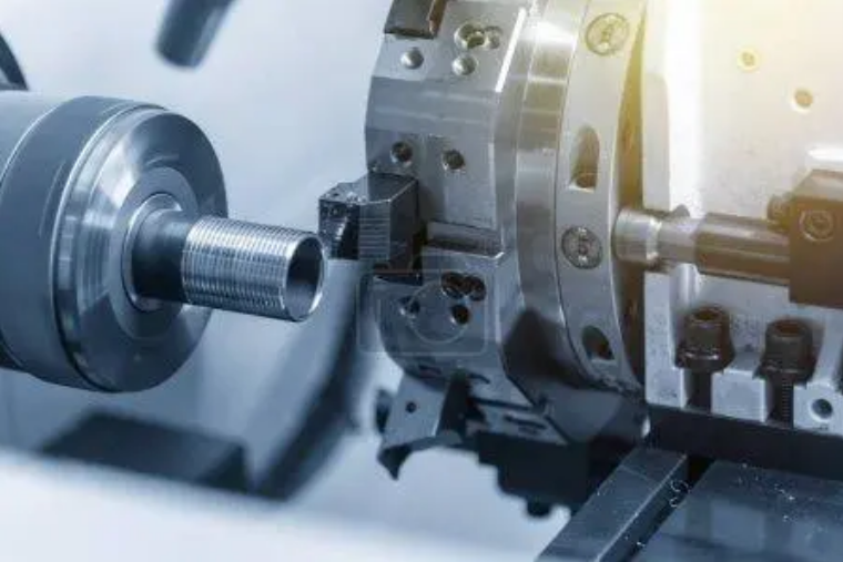
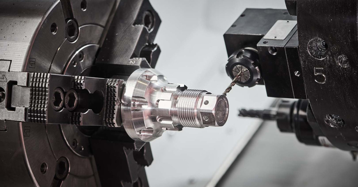
One of the most crucial steps of the process is cutting, a process in which fabrication tools and equipment are employed to cut sheet metal into specific shapes and sizes. Techniques such as blanking, laser cutting, waterjet cutting, plasma cutting, or cutting with stamping dies are used. To achieve a required level of precision, a manufacturer should use CNC laser cutting machines that can be precise to standards as high as +/- 0.005 inches and even below .
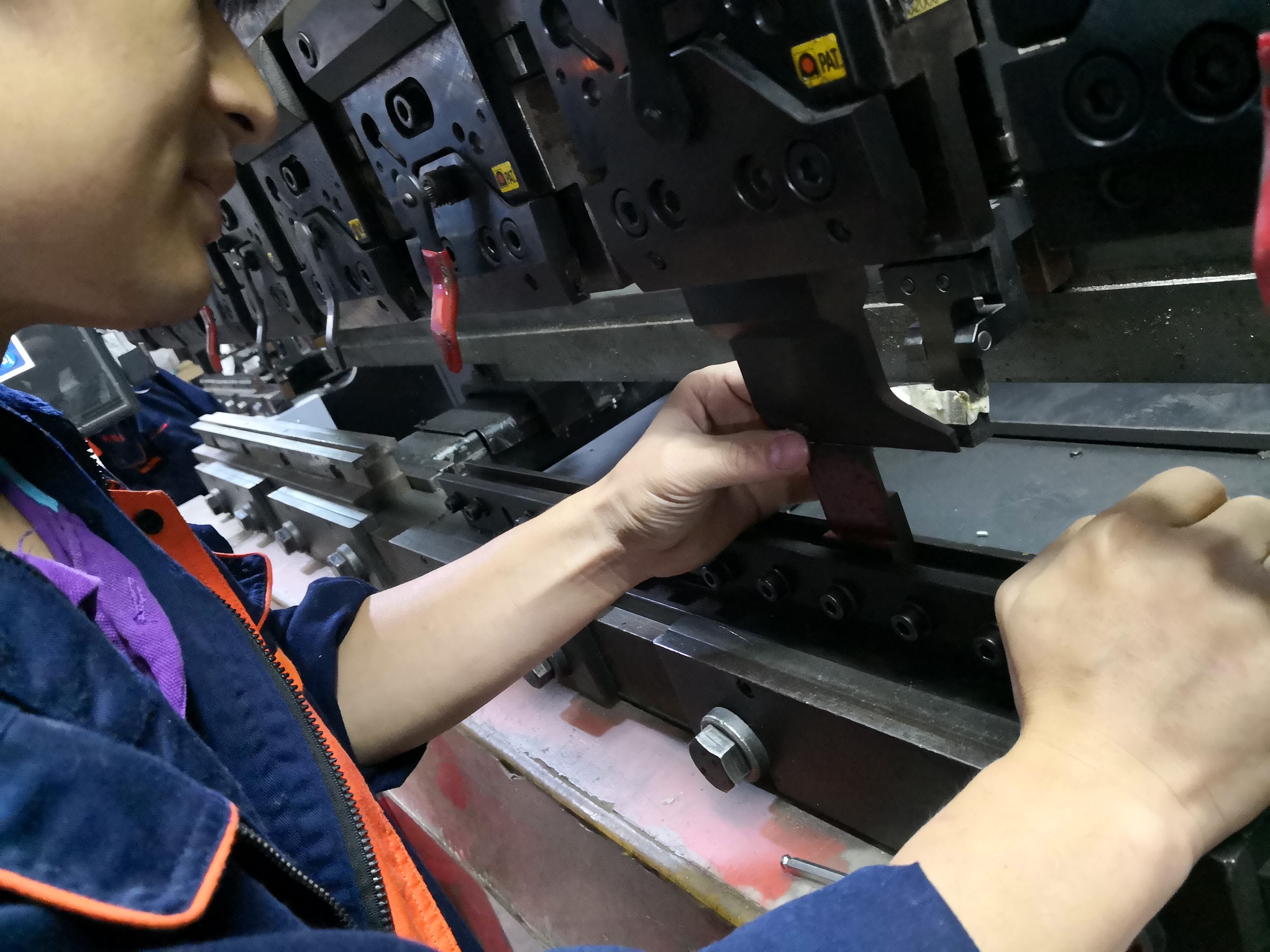
Forming Processes in Sheet Metal Prototyping
At the forming stage, such tools as press brakes and metal stamping presses are used. A press brake is used when a precise angle bend is required. In turn, it is essential in the prototypes that every part fits into another in the finished product, for instance, to create a box. Typically, forming machines are adjusted according to the type and thickness of the metal. It is crucial because at the final product assembly the parts or joints will either be too slack or too tight. However, such a manufactured part should not be thrown away, as the manufacturer can adjust the machine settings and provide the needed angle. Moreover, the formation process can be held without a metal structure change and avoiding hardening, which might influence its further welding. Therefore, adjusted forming is beneficial as it combines the value of flexibility and continuous form. Therefore, the manufacturing process does not involve the machinist deviating from the parameters without designers’ approval.
Assembly Methods in the Sheet Metal Components
Assembly is not only about connecting parts; namely, it is the method, by which every component and part functions together as one unit. For assembly creation, such welding types, as MIG and TIG, are usually used, providing strong and lasting connections. The choices in welding technology depend on the kind of metal applied, as well as on the usage of the final product. In overall, MIG and TIG are the most commonly used welding tools in prototyping sheet metals .
Materials Selection for Sheet Metal Prototypes
Material selection for sheet metal prototypes is a crucial decision for the engineer because the material will not only impact the manufacturing steps but also the final product performance. This decision takes several considerations into account, such as the strength, weight, corrosion resistance, and cost of the metal. Several primary metals usually utilized in prototyping are as follows:
Aluminum: Encompasses the Benefits of Lightweight and Corrosion Resistance
Aluminum has long been the sheet metal prototype material of choice due to its excellent strength-to-weight ratio. Various industries such as aerospace and automotive prefer aluminum because weight reduction is a priority. The common aluminum grades used in prototyping are 6061 and 7075, which are both weldable and very resistant to fatigue. The material thickness varies greatly and can range from as little as 0.016 inches to as much as 0.25 inches, meeting a wide array of applications. Aluminum is distinguished from other metals by its ability to resist corrosion.
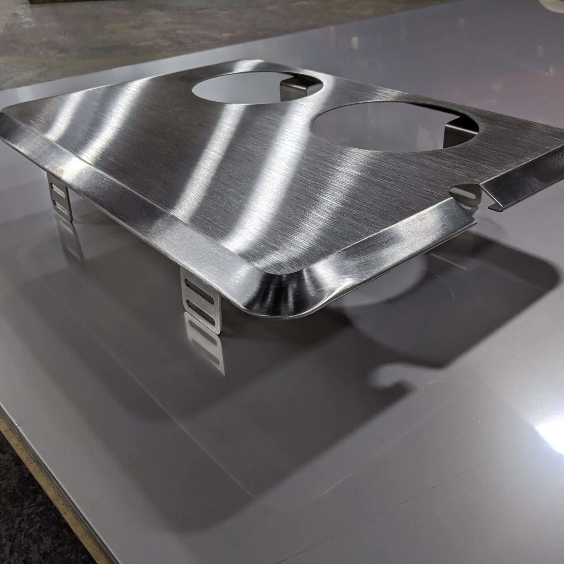
Stainless Steel: Ideal for Both Durability and Aesthetic Beauty
Stainless steel is the material of choice for applications requiring high strength and durability. The most popular stainless steel grades are 304 and 316, both able to withstand harsh environments without corroding. In addition, the material is very visually appealing due to its ability to be polished to an extremely high shine. This feature is often used in food-grade and consumer goods.
Copper: For the Best Thermal and Electrical Conductivity
Copper is vital in electrical elements and heat exchangers due to its exceptional electrical and thermal conductivity. Copper is also very ductile and permits the engineer to use complex shapes while being sure that no cracks will emerge. Often, the engineer has to use copper on prototypes that deal with thermal or electrical, though it is more expensive.
Magnesium: A Dense Metal with High Strength
Magnesium is also a metal available to the engineer in prototyping. This material is seldom used because of its Flammability; sometimes the situation demands a drastic reduction in weight, and fire resistance is secondary. The material density is about two-thirds of that of aluminum, reducing its space requirements and weight. It does not lose its strength, leaving the designer with many benefits.
It is crucial to consider the thickness of the material in material selection, as the material effectively determines the type of processing it can conduct, such as bending and cutting . Thicker materials require more robust machinery and can inflate the production costs.
Designing for Sheet Metal Fabrication
Designing for sheet metal fabrication requires a thorough understanding of the material and its fabrication methods. This is a critical part of the process because it impacts the manufacturability, efficiency, and cost of the prototype. Here are the key principles to follow:
Understand Material Properties and Limitations
Each type of material has its own limitations and properties that affect its ability to be formed and manipulated during fabrication. Designers must select the best-suited type of materials and account for bending radii, minimum hole sizes, and cut widths. For example, aluminum’s flexibility allows for a tighter bend radius than stainless steel, which might crack if bent too tightly.
Implement Standard Design Rules
To avoid simple pitfalls in fabrication, it is important to understand the minimally safe sizes of holes and bends. All holes should be designed to be at least the same diameter as the material’s thickness – otherwise, the tool might get clamped by the press during the punching or drilling fund. Moreover, all bends must have a sizeable radius, at least equal to the thickness of the material, to ensure that the metal does not undergo stress fractures .
Optimize for Fabrication Techniques
The selected fabrication method will also influence the design. For example, laser cutting is relatively cheap and enables highly complex designs and tight tolerances . In mass production, press break forming would often be more applicable but would require simpler shapes. Hence, the fabrication method must be considered when designing the product.
Use Software Tools for Accuracy
Finally, sheet metal design is virtually impossible without a modern CAD tool. Such software allows the designer to create a 3-D model of the part they want to produce, which can be virtually tested for tightness of fit and functionality. For instance, 3-D tools can help identify potential problems with interference between two parts of a design, as seen in the figure below:
Finally, it is important to focus on the overall ease of assembly of the designed product. Individual parts should be connected using notches, tabs, and snaps so that they do not need to be adjusted, measured, and positioned manually. Moreover, there must be adequate room to access all joints in welding or mechanically affixing them.
Cutting Techniques for Sheet Metal
The cutting stage is vital in sheet metal prototyping since it gives the basic form of the prototype. The technique that is best suited for the job depends on the material used, thickness, and design complexity. Each method has advantages and should hence be chosen based on whether it is optimal for the precision needed, the properties of the material, and cost effectiveness.
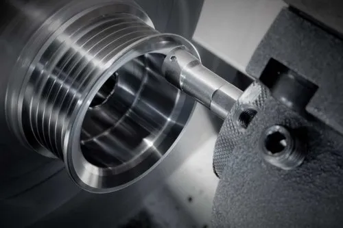
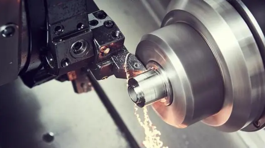
CNC Laser Cutting: The Tool for Precision and Versatility
CNC laser cutting is the best choice for applications requiring high precision, with tolerances of about +/- 0.005 inches. The technique uses a high-intensity laser beam to melt, burn, or vaporize the metal. This allows more complex cuts to be made without having to make physical contact between the cutting tool and the metal itself. Laser cutting is unbeaten for cutting fine details of stainless steel or aluminum metals, and is highly repeatable for production runs.
Water Jet Cutting: No Heat, No Problem
For cutting with no heat, the best tool is water jet cutting for materials that are affected by high temperatures. This process uses a stream of water at high pressure, typically mixed with abrasive particles. This literally cuts through the metals, ensuring no heat-affected zone is produced, which would interfere with the metal’s properties. The water jet cutting can be used for cutting a variety of mediums. It is also very suitable for thicker metal sheets and harder metals that would be hard for laser cutting processes.
Plasma Cutting: Specialized Tools to Cut Thicker Materials
Using plasma cutting is warranted when dealing with thick sheet metals. The metal sheets are heated beyond their melting point by ionized gas which conducts electricity, thereby creating plasma. This technique is especially preferable for sheet metals like steel plates which are over 1 inch thick, as the process is faster than others.
Stamping: An Economic Solution for High Volume Production
Stamping is the perfect solution when a high quantity of metal parts needs to be produced. This cutting technique employs dies and high pressure to cut or shape the metal sheet in one or multiple operations. This is especially more practical when it is the same part that needs to be produced in high quantities, as the larger costs associated with the creation of dies is spread across the variety of pieces produced.
Forming Processes in Sheet Metal Prototyping
Forming processes are typical for sheet metal and are used to give the metal shape and meaning. There are several ways in which a piece of metal may be manipulated, including bending, stretching, and stamping. Each of these methods has its effect on the piece of metal and can be utilized depending on the task at hand.
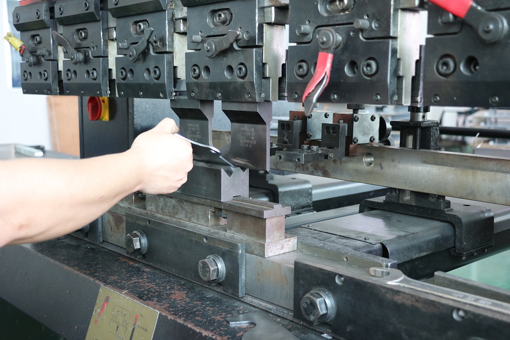
Bending
In forming, bending is amongst the more usual processes, and it is used to create V-shapes, U-shapes, or channels in sheet metals. The most typical machine utilized for bending is the press brake, and the precision of bends created using one can reach +/- 0.5 degrees . The radius of the bend should be at least equivalent to the thickness of the piece of metal, or the metal risks cracking or bending beyond the elastic deformation.
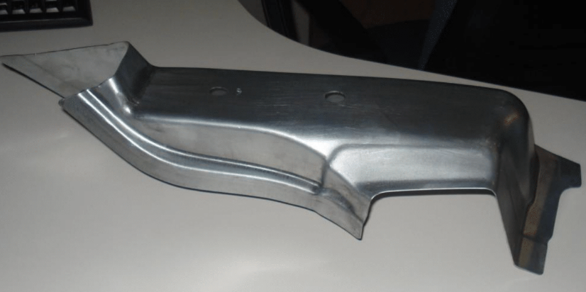
Deep Drawing
The deep-drawing process consists of pulling a sheet metal blank into a die to create a deep, hollow form, such as a pot or a sink . This process is used when the component that is being created requires a significant thickness in relation to its diameter. One of the critical parameters in deep drawing is the wall thickness and how the material flows into the die and results in the creation of different displacements.
Stretching
In this process, the piece of metal is elongated using tensile force and can be done using a stretcher. This forming process is mostly used to create smooth, large-radius curves and is used mostly in aerospace and automotive panel construction . Stretching is used id the design requires a smooth uninterrupted part of the material.
Assembly Methods for Sheet Metal Components
In the prototyping of sheet metal, assembly methods serve the purpose of combining individual parts into a single functional item. Various advantages of each method depend on the matrix applications, the sheet metal material, and design characteristics. Proper assembly should provide a functional structure and sufficient strength level.
Welding: Strong and Durable Joints
Metal sheet prototyping frequently relies on welding as the go-to solution for joining components due to its strength and relative permanence. Metal Inert Gas and Tungsten Inert Gas welding are commonly used. However, the latter is often applied in aerospace mechanisms and automobiles because it allows for clean and accurate welding, and the former is better for thicker sheets and can provide more speed and, therefore, economy . However, maintaining a proper temperature and control of the welding process may be required if the goal is to avoid the weld joint warping and the metal overheating to the point of weakening.
Rivetting: Robust Mechanical Connections
Rivetting is comparable with welding in strength and offers a different kind of assembly which involves connecting metal parts using metal pins aligning the source. It is beneficial to the welding process because it does not require application of heat, and, thus, is more suited for assemblies of materials sensitive to high temperature. Moreover, rivets, universally made out of metallic alloy, typically offer excellent shear and tensile strengths . Rivetting is commonly used for aircraft parts and bridges. The main disadvantages of the method are that the rivet material should be properly chosen depending on the mechanical load and the lack of visible loosening or damage detection.
Screwing and Bolting: Design Versatility and Component Reuse
Screws and bolts are the go-to option if the assembly needs to be disassembled. They are generally easy to handle and can often be used for guiding the overall assembly. Screws and bolts also allow for the proper adjustment and, at times, replacement of the assembly without the source suffering damage. These features make them well-suited for prototypes.
Testing and Refining the Prototype
Sheet metal prototypes must be tested and refined before they can become mass-produced goods. This stage demands that a prototype be well-evaluated and rigorously tested in order to ensure that it meets all the requirements and goals of the design.
Functional Testing
Perhaps the most important type of testing, functional testing costs whether the prototype performs its intended function. This includes such tasks as load-bearing, durability, and fatigue testing, which simulates the environment in which the product will be used . A sheet metal product designed to serve as a part of an operating machine might be subjected to a degree of stress in this way to ensure it does not deform or become unusable.
Aesthetic and Fit Testing
Another crucial design requirement is that the process passes aesthetic and fit testing. Here, one is required to check if the part fits the machinery it is intended to serve, without any gaps between the component and the slot it is intended for. Another important requirement is the surface finish quality, as any marks or scratches will need to be minimized to produce as good of an appearance as possible. A sheet metal box that is intended for sale and has to be attractive to customers would be subjected to these types of tests.
Environmental Testing
Finally, a prototype should be tested to see if it can resist the environment it will be exposed to. Such factors could be temperature, humidity, or chemicals found in the environment. Corrosion is perhaps the most common test here, as many sheet metal products will be expected to survive the harsh climates found in the outdoors, where frequent contact with water is common. A testing procedure such as a salt spray test, which incorporates a simulation of several years of exposure to corrosive environments in several days, may be used .
Refinement and Iteration
Prototypes must be improved based on the results of the tests. It may require altering its design, its material, or the method of fabrication. Eventually, the combination of all of these factors will result in a fit-for-purpose and attractive sheet metal design that meets every customer and market requirement.